Remote Controlled Switch Circuit Diagram
Remote Controlled Switch Circuit Diagram
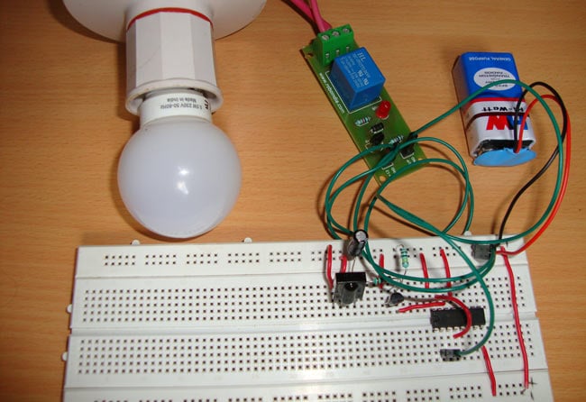
In this remote controlled switch circuit we are using TV remote to ON/OFF the AC light by pressing any button of remote, and using the TSOP1738 at receiver end. Receiver circuit is connected to AC appliance via Relay, so that we can control the light remotely.

Smart Home 433Mhz RF DC 2CH Learning Code Wireless Remote Control Switch Relay Receiver Transmitter Universal Remote Switch System and Long 500M RF Transmitter Remote Controls 1527
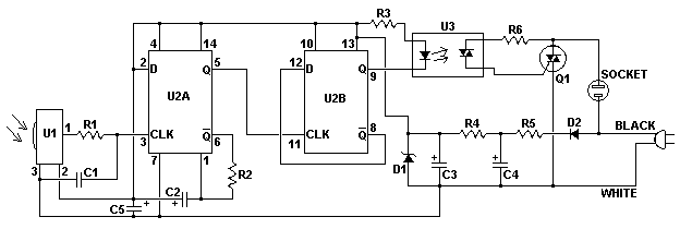
IR Remote Switch Circuit
Remote Controlled Light Switch - ElectronicsHub
Electronic Schematics Remote Control
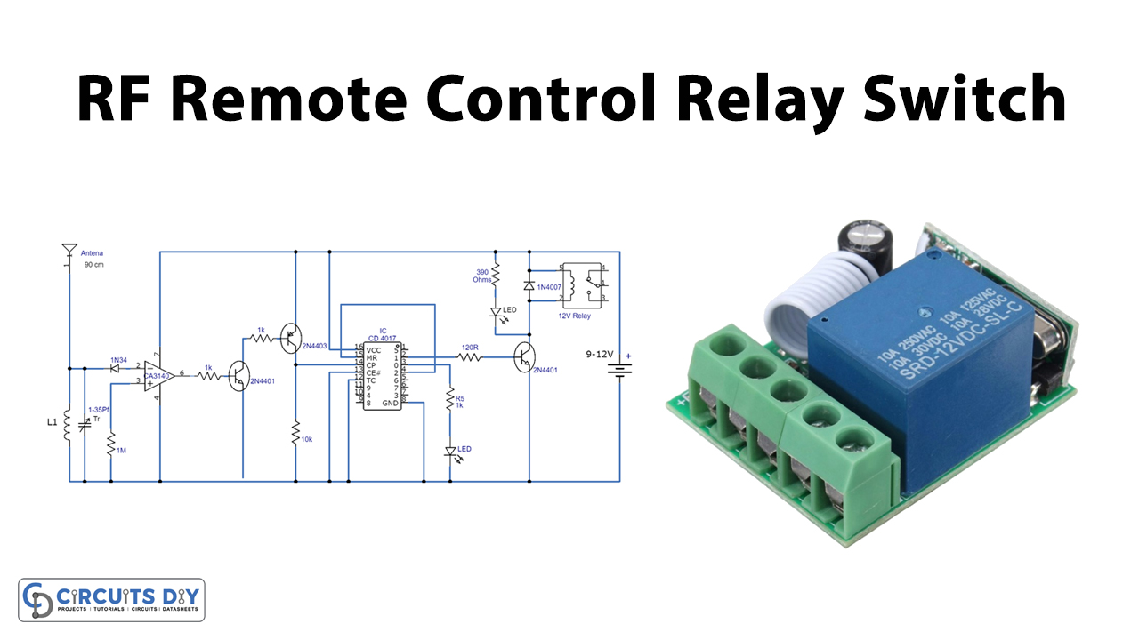
RF Remote Control Relay Switch
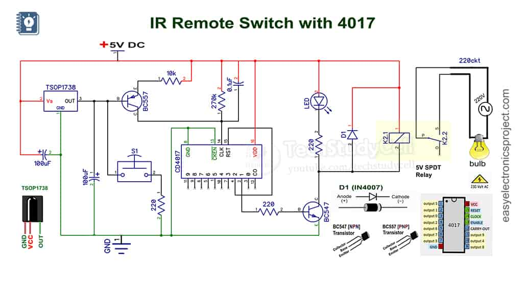
IR Sensor Switch with IC 4017 project - Electronics Projects
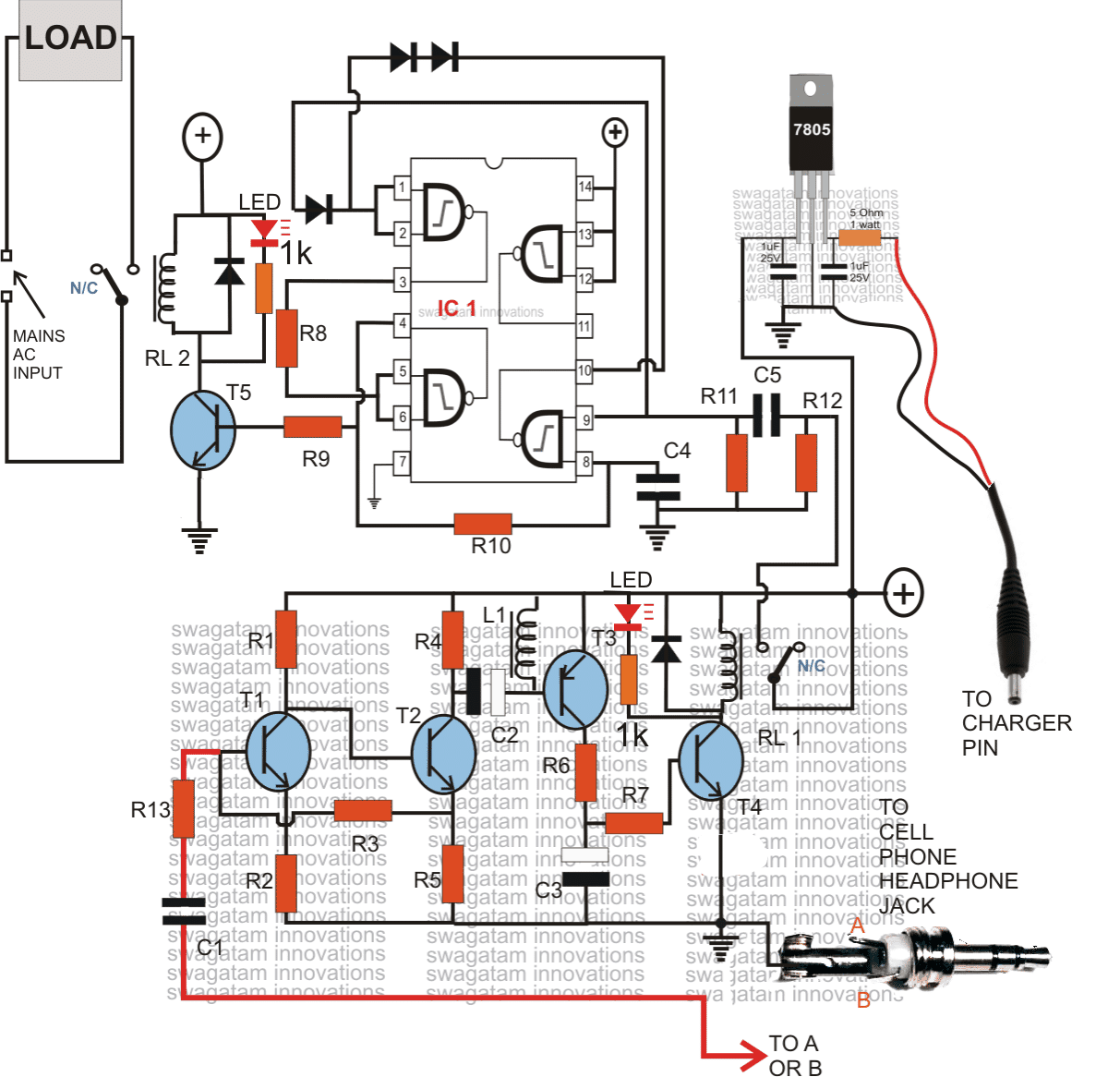
GSM Based Cell Phone Remote Control Switch Circuit

Remote Control Switch - EasyEDA open source hardware lab

Remote Control Switch on/off Can Operate Fan/Lamp etc Follow @wa_electronics for more like this. Like❣️ comments📋 Share📤 Keep…

remote control switch circuit diagram in 2023 Circuit diagram, Electronic circuit design, Electronic circuit projects


